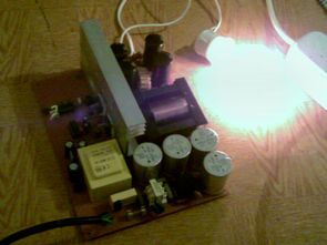
Sg3525 Ir2110 Smps Rar Average ratng: 4,8/5 6794reviews. Hi, I am new to the forum my congratulations for the nice work going on, especially to Microsim,Ludo,Luchini, khron,kaip,michelle,stewin and others. I have some doubts to clear in your smps project. Jan 05, 2019 Sg3525 Ir2110 Smps Rar; Sg3525 Ir2110 Smps Rar. Half bridge method with different versions of the techniques used SMPS circuits test picture diagrams and photos seen in the application’s PCB file available control ICs TL494, SG3525 as a drive transformer and IR2110 used there are designs that applications design can assist you. 500W 1000W SMPS circuits schematic pcb diagrams all files: 500w. Smps details, 2 x irf740, ir2153, run freq is 100khz, protection use current sense trafo, 4x 1n4148 + mcr100, output voltage +43.5 and -43.4, output diode mur420 x4, output inductor 25+25 laps awg 18. Today im testing this smps with 200wrms discrete class D and solidstate with 8 output transistor (4 x 2SA1302 + 4 x 3281).


Sg3525 Ir2110 Smps Rarity Chart
Sg3525 Ir2110 Smps Rarity Guide
SG3525 Circuits SG3525 Projects SG3525 pulse width modulator PWM control integrated, can be used for the control of all kinds of switched power supply. High performance. A synchronization input to the oscillator allows multiple units to be supplied or a single unit to be synchronized to an external system clock. A wide range of dead time control can be performed with a single resistor connected between the Frequency and Discharge pins, plus a built-in soft start circuit set by an external timing capacitor.